Wednesday, 8 June 2011

Week 12 Stairs

REFERENCE TO STAIRS AND DECK REGULATIONS

When making stairs and choosing the correct size stringers, use the joist table in Nzs 3604 to select the correct span for the length of the stairs. This will also apply to the treads in handling the load of standing on them. 


CONSTRUCTION OF A DECK OVER 1M HIGH WITH ACCESS STAIRS
• B1 Structure: B1/AS1 construction and framing generally complies with NZS 3604 or where the
deck is over 3m high, specifically engineer designed using NZS 4203.
• B1 Structure: B1/AS2 for timber barriers. Other barriers require specific engineering design to
NZS 4203.
• B2 Durability: B2/AS1 with timber members are treated in accordance with NZS 3602 and
fixings to NZS 3604.
• D1 Access routes: D1/AS1 for stair dimensions, slip resistance and handrails.
• E2 External moisture: E2/AS1 particularly detailing the junction between deck and house.
• F4 Safety from falling: F4/AS1 as an area frequented by children under 4 years.


LINK TO PDF OF NZ WOOD STAIRS TO CODE


Tuesday, 17 May 2011

WEEK 8 Solid nogs and Trim out

WEEK 8 Boundary joist

BOUNDARY JOIST
 Setting the boundary joist and clamping the mitre cut for fixing, when joining to boundary joists together. The team, here is happy with their work. Nail the boundary joist with 3 nails to each floor joist end. 25mm in from top and bottom edge amd one the middle.

Arlee is getting those notes down on what he has done for that morning. It is important to fill out the portfolio out everyday and 3 times a day. Fill out the material list, self assessments and the tool box talk.Transfer notes on what you have learnt and done that ay onto your blogger.

WEEK 8 Joists

FLOOR JOISTS
Bearers already for marking out joist spacing, wall positions and where service waste lands. Marking position for timber is marked clearly with a bold line and a X on one side of that line. The X indicate that is where the timber is positioned.

Once bearers are all marked out, set the joist on the X mark. Sorting out where different treated timber and lengths are required in floor plan.


 Joist are all laid out and positioned with side of the house that is 15mm in from the outside edge of the bearer. This for the 30mm overhang of the boundary joist.

Once the 30mm overhang is positioned, check this with your stringline. Check the other side of the house and the overhang of the joist over the bearer will be 330mm to the stringline, then run another stringline -47mm from the 330mm stringline for boundary joist. Use a combination square to mark a plumb line from the singline, cut all joist to that -47mm line.

Monday, 16 May 2011

WEEK 7 Floor joists

FLOOR JOIST
The floor joists are sorted from the packet to see if the right lengths and quantity were delivered to site. The joist packet allowed for H3.2 joist in the kitchen.

Mark joist to plan and consider where walls land and service pipes will be ie. Toilet and shower waste pipes.
How do we provide a service area if a joist is in the way of a waste pipe?

Friday, 6 May 2011

WEEK 7 Jack studs

Once the sole plates are fixed into position, jack studs were nailed to the sole plate at 1600mm centers to the plans specifications.

Johnny and Arlee here cutting the jack studs to leveled height of the set string-line.


Once the jack studs are all cut to the -400mm from FFL, the bearers sat on top of the jack studs and fixed by two 100mm skewed nails to each jack stud, one each side of the bearer.

The jack studs and bearers are braced off and plumbed and measured for the correct width acording to the bearer plan.

What is the width from outside to outside of the bearers?
What is the measurement to the center.

If this is all correct, how would it make the next stage easier when installing?  


Tuesday, 3 May 2011

WEEK 6 Profiles and footing

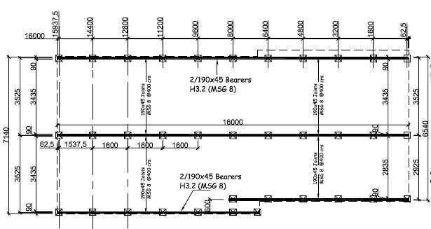
BEARER PLAN
This shows where the foundation footings will be for the sole plates, jack studs and bearers to be positioned.


PROFILES
Building line has been set and footing lines was set also, for the Sole plates and Jack studs.


WEEK 6 Profiles

SETTING OUT PROFILES

Profiles are timber constructed frames to find the height of a finished floor level and the boundary of the building (house).
Profiles are a minimum of 900mm away from the marked peg (boundary of the building). 

PROFILE PARTS

Make sure the construction of the profile is sturdy, bracing will achieve this from moving. This is important when you start setting the string-line to find the building line it will not move and put the building (House) out of square.

WEEK 5 Start building the Unitec house

EXCAVATION

The site for the house to be built on was over grown with weeds and vegetation. This has to be cleared to reach solid ground and clear for marking out the location of the house.


The site is now cleared and looks a lot tidy for working on and marking out for profiles. This also makes the site safe from tripping over, standing on hidden sharp objects, twisting ankles. 

SETTING OUT LOCATION OF THE HOUSE

From the plans we set out the location of the house on-site, marking from the boundary of the property and measuring in from two boundary sides, we get the starting points to where the house is located on the site.
From here we can plot out the rest of the perimeter of the house using right angles from the formula 3-4-5. 


Depending on the shape of the house we can now work off these two sides and plot the building line of the house. Now we can set our profiles to each corner of the building line.

Monday, 11 April 2011

WEEK - 5 Site Safe

Wednesday 6th Site Safe


CCA1 Class completed the Site Safe course and enjoyed the session with Colin O'Gorman.

Wednesday 6th Site shed

Tuesday, 5 April 2011

Week 4 - First Aid

First Day at First Aid

This is a video of First Aid trainer Rowan showing how to roll a large person onto their side.


Jordan and Lenny demonstrating how to bandage a cut hand by Rowan (First Aid trainer)  
Deep hand cuts keep the pressure on with a roll of bandage or rolled up cloth, towel or piece of clothing. Then bandage over closed hand that is holding pressure to the cut.


Do not remove rebar, this will cause more damage and bleeding. Apply pressure around the rebar with bandage or towel to stop the bleeding.


WEEK 4 - Induction to Profiling


Induction in the equipment used to set up the profiles. 

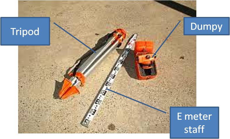
Dumpy level is a an optical instrument used in surveying and building to transfer, measure, or set horizontal levels
The Dumpy is mounted on a tripod to sit at eye level for operation and uses a measuring staff to focus onto for reading horizontal levels.

The Dumpy level

 
Setting the dumpy and finding the horozontal level of the first corner of the house.

 About to focus onto the first corner of the house.
 .
 
 Ah Chee's group is focusing on the seond corner of the house, They have the first corner height and subtracted the dumpy level height from the FFL. Then collecting the readings from the other two corners.

1. If the four corners are all the same reading, is the house level? 

2. If the readings are not the same, is the house level?

3. If the house is not level, how can you find out how much it is out of level?


WEEK 3 - Saw Stool

WEEK 1 - Hand Tool Exercise

WEEK 2 - The Saw Stool

How to  find 1 and 3 Angle
 The notes on the Saw Stool are how to find the 1 and 3 angle and what hand tool to use.


Sliding Bevel Hand tool for finding and setting angles.

Working out the length of the Saw Stool leg using 1 and 3 angle.

Using Pythagoras we can work out the length of the leg.  
Record your the notes as well as your own, this will help you with future task to come.

Chiseling the housing for the Saw Stool leg to fit.
 Antonio practicing one of many crafts. The craft of chiseling and soon to be Master carpenter.

Wednesday, 16 March 2011

WEEK 2 - The Workshop Machines


The start of the Saw Stool

After completing the timber joint exercise, the students are now trying their new found skills on making a Saw Stool.

Wednesday morning students started measuring, cutting and machining their timber to fit the right size from the cutting list in the portfolio.

They used 3 workshop machines to complete this task.
1. Radial arm saw
2. Table saw
3. Thicknesser


The students were inducted with Health and Safety of the machinery and the operation of the machines.


Green button (ON) Red button (OFF)
IT IS IMPORTANT TO TURN ON THE DUST EXTRACTOR WHEN USING THE MACHINARY, THIS PREVENTS DUST AND WOOD CHIPS CLOGGING THE MACHINE. THIS ALSO PREVENTS CAUSING DAMAGE TO THE MACHINE AND TO YOURSELF.
What other switches are used before you can operate the machinary in the workshop?

Main ON/OFF switch


What does this main switch do?


WORKSHOP LIGHTS
Where is this located in the workshop?

 
RADIAL ARM SAW
What are the safety rules when operating this machine?

 
RADIAL ARM SAW
What are the operating buttons on this machine?

TABLE SAW
What are saftey precautions that you should be using before operating this machine?

ELECTRONIC THICKNESSER
How do you find out the setting of the table lift to plane the first layer of the timber?
What is the recomended amount of timber to plane of at a time?
THICKNESSER CONTROL PANEL
Name the four buttons that are used to operate this machine?
When you press the start button, what should you do before putting your timber in?

What is the RED button on the back of the Thicknesser?